Construction of a Kibble Balance—The Device that Redefined the Kilogram
Construction of a Kibble Balance—The Device that Redefined the Kilogram
2018 SPS Chapter Research Award
Project Lead: John Evans
SPS Advisor: Donna Hammer
Project Summary: Physicists have redefined the kilogram in terms of a natural physical constant using a Kibble balance (previously known as a “watt” balance), which measures mass by balancing opposing gravitational and electromagnetic forces. Here, we undertake the construction of a high-precision Kibble balance using low-cost and open-source hardware, in collaboration with UMD Physics Makers. We are implementing an asymmetric balance-wheel design modeled after the NIST-4 Kibble balance. Our Kibble balance is designed to be constructed by undergraduate students and give them opportunities to acquire skills in computer-aided design (CAD), electronics, 3D printing, machining, programming, data analysis, and optics.
 Imagine the chaos that would ensue if the definition of a meter or a second varied from place to place. Standardizing our base units—the second, ampere, meter, kilogram, kelvin, mole, and candela—is essential for modern industry and research.
The kilogram, the base unit of mass, was first defined in 1795 as the mass of one liter of water at 4°C. In 1889, the kilogram was redefined as the mass of a specific cylinder made from a platinum-iridium alloy. That cylinder, called the international prototype kilogram (IPK), is stored just outside of Paris, France, and remained the mass standard until this spring. On May 20, 2019, the kilogram became the last of the base units to be redefined in terms of the fundamental constants of nature. The definition of the kilogram is now tied to Planck’s constant, a value measured precisely with the state-of-the-art NIST-4 Kibble balance at the National Institute of Standards and Technology (NIST).
Inspired by a do-it-yourself LEGO watt balance designed by NIST researchers for education and outreach, physics students at the University of Maryland decided to create an inexpensive, high-precision Kibble balance that can be constructed by undergraduate students with access to a workshop. After building our own Kibble balance, we plan to release instructions that can be used by other SPS chapters.
A Kibble balance determines an object’s mass from the force required to offset its weight. The Kibble balance has two measuring modes that work together: the force mode and the velocity mode. In the force mode, a test object is placed above a wire coil. The object exerts a downward force equal to its weight. A current is applied through the coil and adjusted until the upward force of the induced magnetic field counterbalances the downward force of the object, and then that current is measured. In the velocity mode, the object is removed and the current is turned off. A voltage is induced by moving the coil through the magnetic field at a constant velocity. The velocity of the coil and the induced voltage are precisely measured. Since the coil and magnets are the same in both operations, the mass of the object can be calculated from the measurements of current, voltage, and velocity.
After meeting with scientists and engineers working on
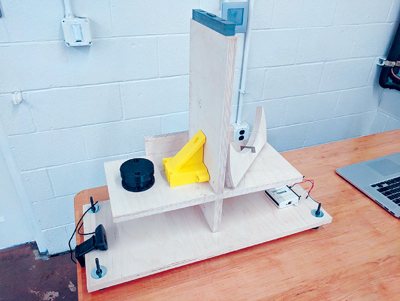
NIST-4, we settled on a design. The next step was to select magnets for running current in the wire coil. We determined that two ring magnets would be ideal and chose neodymium magnets with an inner hole diameter of 0.25 inches and outer diameter of 2 inches. We then 3D-printed a structure to house the coil and magnets. Informed by simulations and calculations, we made a 3,000-turn coil of 36-gauge magnet wire. Given the coil and our other equipment, we expected to be able to handle a mass of 30 g.
Our main goal in designing the balancing mechanism was to create a low-friction contact between the mechanism and a supporting wood frame. We made a balancing wheel out of wood that balances on top of a tungsten carbide pivot mount via a razor blade. Grooves on the outer circumference of the balance wheel guide a titanium wire that connects it to a stepper motor, the mass pan (which holds the test mass), and wire coil. A counterbalance keeps the entire apparatus balanced during operation.
In velocity mode, we drive the coil through the magnetic field with a motor. Our original intention was to build an interferometer to measure the velocity of the coil housing, but we could not complete our interferometer in the time given. We ended up using a webcam to measure the position of a brightness contrast on the mass pan and were able to achieve positional precision of +/- 0.2 mm over 50 mm of travel.
We have yet to get to the point where we can press a button and measure a mass, but we are close. We have a design that works well and software that completes every aspect of calibration automatically. Our data acquisition device has been difficult to interface with, but we expect to have this figured out soon. We look forward to using this device at outreach events and conferences.
This was an amazing opportunity to develop and manage a research project. Ten SPS members were actively engaged, honing their skills in design software, woodworking, programming, and data analysis. The biggest lessons that we have learned are the importance of dedicated, committed group members and securing necessary resources (like a suitable workspace) early on. If you are considering applying for a chapter research award, we recommend a strong emphasis on recruiting interested and committed individuals and securing proper guidance. Also, make sure that your project is manageable in conjunction with a heavy academic workload.
Team members: John Evans, Brady Easterday, Paul Neves, Brandon Grinkemeyer, Matt Marks, Matthew Spooner, Stephanie Williams, Peter Zhou, Brendan Van Hook, and David Long.
For more details on this project, visit our SPS award page at spsnational.org/awards/sps-chapter-research-award/2018/university-maryland-college-park.
